[] PID BLDC motor control with Arduino
HKUST Class Project: Introduction to Embedded Systems
🤖🤖😭😭
Project introduction
This Project is to make a two-wheel robot that can balance. Balancing is achieved with a flywheel that spins to always keep the center of mass of the robot in the center.
# A CAD model illustration of the finished final productComponents
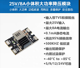
- 12V to 5V buck converter
- 12V to 24V voltage booster
- MPU6050 gyroscope
- Battery
Result
I was not able to complete the balancing PID before the deadline, therefore the electronic system was never put on the robot prototype.
However, achievement has been made on the PID control on the BLDC motor. Progress was also made on the PID balance algorithm.
Other functionalities of project
- Reading the velocity of the motor shaft, with update rates of 100hz
- Control the speed of the BLDC with timer-implemented PWM and GPIO_OUTPUT
- Read acceleration and gyroscopic data from MPU6050 at a rate of ~1000hz
- Processing MPU6050 data with complementary filter and dynamic mean algorithm at a rate of ~ 1000hz
- A mode selection feature for debugging. The mode is selected by the K1 and K2 onboard buttons, and the
mode number is displayed on the built-in LED in binary format
PID control functionality demo
I was able to get some cool PID control running on the motor with the STM32.
- Position PID control
- Velocity PID control
- Physical knob button simulation (feeling of discrete levels)
At the end of the video shows the attempt of balancing a stick with a flywheel. Although unsuccessful, you can see the flywheel reacting to the angle of the stick, causing a back and forth oscillation (theoretically if the the oscillation is small enough then the balance will be successful)
PID balance function testing
This is the prototype board I hand-made before designing and ordering the PCB. It was used to test the functionality of the BLDC motor and the MPU6050 gyroscope.
The setup as a simple stick that connects the motor and mounted with the gyroscope. The goal was to balance the stick on its own. This was the part I spent a few weeks on and got stuck.
Extra information
Electronics
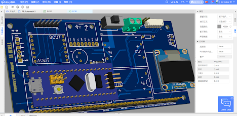
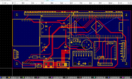
I used EasyEDA to design the PCB that connects all the electronic components and provide power to the robot.
The 2-layer PCB has the following features:
- Connectors for motors and servo motors
- Independent power capacitor for the STM32
- Mounting hole for the PCB to the robot frame
- Power polygon traces for power supply and motors
- Power switch
Prototype
I used Fusion360 to design the body of the robot, and manufactured it with TaoBao suppliers
We didn't have time to finish assembling the robot


